This method is used for pre-event site survey records. It applies to mobile stage and roadshow vehicle projects.The purpose of a site survey is not simply to collect photos. It is to confirm four types of constraints in advance:Whether the vehicle can enter the site;Whether there is enough space for structural movement;Whether the support system can land stably;Whether on-site systems can be organized smoothly.
What Information Should Be Recorded and What It Affects
1) Entrance Clear Width and Passing Clear Height
Entrance clear width affects whether the vehicle can pass through and whether there is enough space for passing or maneuvering. The tighter the entrance is, the easier it is for the vehicle to scrape against gate posts, guardrails, or parked vehicles.
Passing clear height affects whether lintels, canopies, tree branches, overhead cables, or similar obstacles may restrict vehicle access. It may also affect later movements such as roof lifting or LED screen lifting, especially when these actions need to avoid overhead obstacles.
Recommended records:Photo of the narrowest point;Photo of the lowest point;Measured width and height range available on site.
2) Turning Points and Obstacle Positions
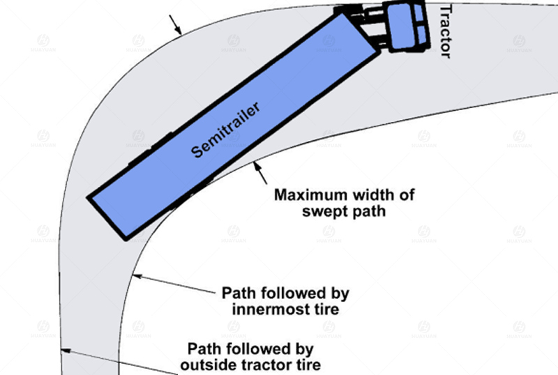
Turning conditions determine whether the vehicle can enter the deployment area along the planned route.
For trailer-based solutions, turning points also create two common risk areas: off-tracking and tail swing.
Inner-side obstacles, such as curbs, flower beds, and guardrails, are more likely to affect the inner wheel path and may cause scraping on the inner side of the vehicle.
Outer-side obstacles, such as parked vehicles, walls, and columns, are more likely to affect tail swing clearance and outer-side maneuvering space.
Recommended records:A continuous short video before and after the turning point;The video should include both obstacles and road boundaries in the same frame
3) Slopes, Height Differences, and Uneven Ground
Slopes and uneven ground affect positioning, support landing, and leveling efficiency. They may also affect the stability of hydraulic movements.
When the slope is obvious, leveling may take longer, and small positioning errors can become more significant.
When the ground has uneven areas or local potholes, the support points may carry force unevenly. Support pads may be required, or the positioning point may need to be adjusted.
Drainage channels, manhole covers, and soft ground may affect the contact area and load reliability of the support points.
Recommended records:Side photo of the slope;Description of the slope location;Close-up photos of the ground, showing material and surface condition
4) Deployment Area Clearance and Boundaries
The deployment area needs to meet two conditions at the same time: ground-level boundaries and overhead clearance.
This affects roof lifting, LED screen lifting, lighting and audio placement, and pedestrian access planning.
Ground-level boundaries include the available length and width of the deployment area, as well as the position of nearby obstacles. These factors affect whether the side wings can open fully and whether access routes need to be adjusted.
Overhead clearance includes tree branches, light poles, signs, billboards, and overhead cables within the deployment range. These may limit the lifting height of the roof or LED screen. In some cases, the parking point or deployment direction must be adjusted.
Wind exposure and surrounding blockage should also be checked. If the deployment area is located in a wind opening or an open corridor, the roof and screen may face stronger wind impact. In this case, fixing methods and safety boundaries should be planned more conservatively.
Recommended records:Full view of the deployment area;Photos of all surrounding boundaries;Photos of the lowest overhead point
Quick Review
Short Record Version
1. Used for quickly checking whether obvious restrictions exist.
2. Photos of the narrowest entrance point and lowest passing point
3. Continuous short video of turning points
4. Side photos of slopes or height differences
5. Full view of the deployment area and overhead environment
6. Close-up photos of the ground, including material and softness
Standard Version
Used for pre-event positioning and deployment confirmation.
Based on the short version, add:
7. Entrance clear width and height range
8. Deployment area length and width range
9. Notes on key obstacles around turning points